Mcdonnell Miller 67 Wiring Diagram
67 Lwco Wiring Torubles Steam Heating Help The Wall

Water Feeder Wiring Diagram Wiring Diagram Data
Wiring 120v Lwc On Millivolt System Heating Help The Wall

Mcdonnell Miller 149400 Model 67 Low Water Cut Off

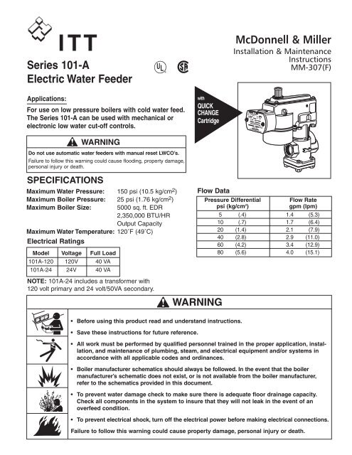
Warning Before Using This Product Read And Understand

Mcdonnell Miller 67 M Low Water Cut Off W Manual Reset
They provide a positive and economical way to detect change or loss of air flow velocity caused by closed damper or fan inlet a loose fan wheel a slipped or broken fan belt a dirty or clogged filter or an overload on a fan motor switch.
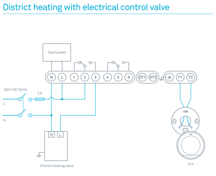
Mcdonnell miller 67 wiring diagram. A wiring diagram is a kind of schematic which utilizes abstract pictorial icons to show all the affiliations of elements in a system. Mcdonnell miller 67 wiring diagram what is a wiring diagram. Mcdonnell miller is a leader in engineering and manufacturing boiler controls liquid level controls low water cutoffs and flow switches for steam and hot water boilers in industrial commercial and building trades applications. Does not make a difference which one.
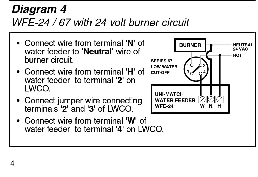
Mcdonnell miller air flow switches sense air flow or no air flow by responding only to velocity of air movement. For 67 low water cut off installed with mcdonnell miller series 101 a water feeder for the 120v burner 120v feeder setups. Assortment of mcdonnell miller 67 wiring diagram. Feeder to neutral wire of burner circuit.
Also other products like heat pumps gas meters gas regulators pressure gauges pressure regulators control valves globe valves open close ball valves butterfly valves valves with rotary actuators ball valves are pressure independent. Basic wiring mcdonnell miller lwco water feeder wiring 24v burner 120v feeder 120v burner 24v feeder series 67 lwco 101a feeder 120v burner 120v feeder 24v burner 24v feeder these are suggested wiring diagrams but not the only solution to a particular installation. Summary of contents for mcdonnell miller uni match wfe 24. A wiring diagram is a streamlined standard photographic depiction of an electrical circuit.
Mcdonnell miller low water cutoff wiring diagram wiring diagram is a simplified okay pictorial representation of an electrical circuit it shows the components of the circuit as simplified shapes and the knack and signal friends between the devices. Page 4 diagram 5 wiring diagram legends wfe 120 67 with 120 volt burner circuit bold lines indicate action to be taken connect wire from terminal n of water in step shown. Wiring layouts are composed of two things. Burner 120 vac supply 12 34 n h 101a 69 c.
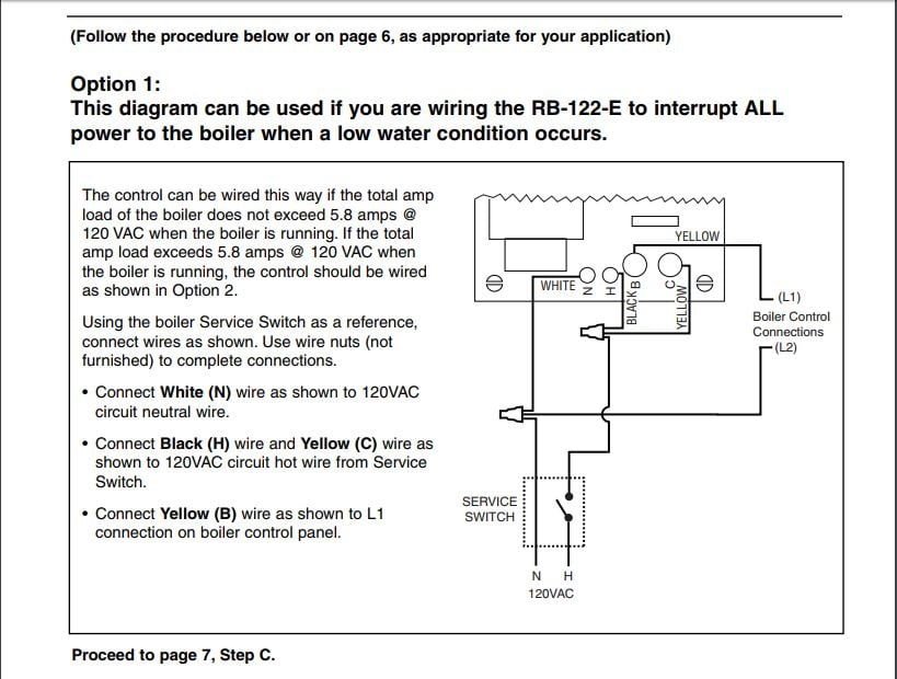
Mcdonnell miller 67 wiring diagram what s wiring diagram. A wiring diagram is a simple visual representation of the physical connections and physical layout of an electrical system or circuit. Using a wire nut connect a wire from the neutral side of the power supply to one of the wires inside the feeders junction box. It shows how a electrical wires are interconnected and will also show where fixtures and components may be attached to the system.
Symbols that stand for the parts in the circuit and also lines that stand for the connections between them.

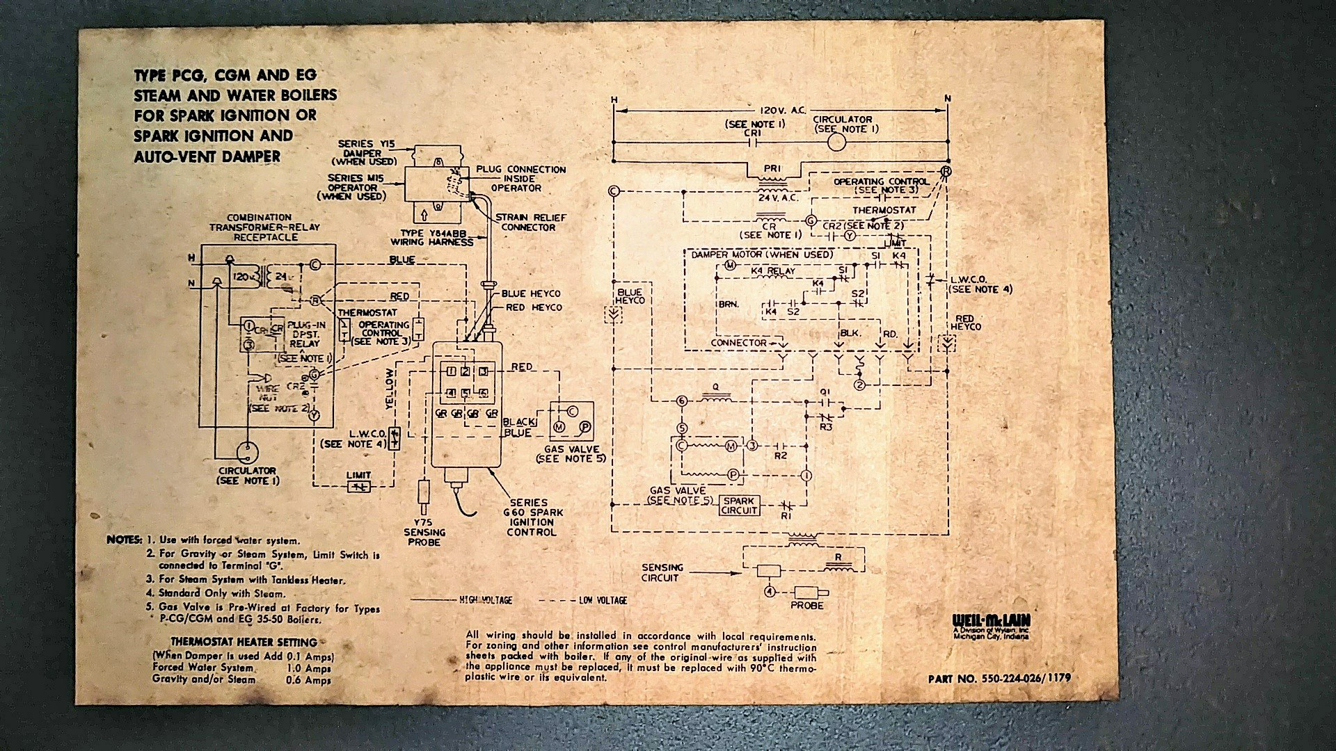
Gas Fired Natural Draft Steam Boilers Installation Instructions
Series 101 A Electric Water Feeder Mcdonnell Miller
Replacing Low Water Cut Off Float Type Page 3 Heating Help
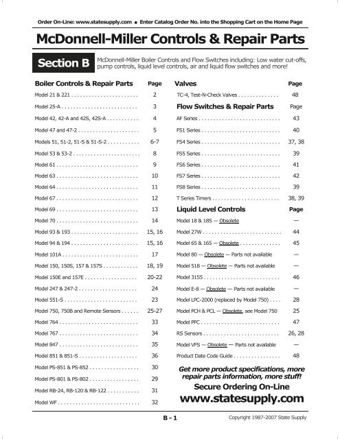
Mcdonnell Miller Controls Repair Parts Categories On Acme
33 Low Water Cutoff Wiring Diagram Wiring Diagram List
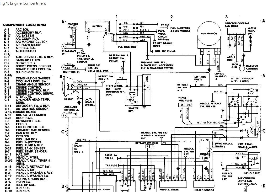
1d0 1990 Nissan 300zx Engine Wiring Harness Wiring Library

C508 Mcdonnell Miller 67 Wiring Diagram Digital Resources

C Wire Help Heating Help The Wall
