Mb 1000 Arduino Wiring Diagram
Mb7389 X Arduino Tutorial With Code Examples Maxbotix Inc

Arduino Schematic This Simple Schematic Will Be Used As A First Wiring Project With Images Arduino Cool Tech Microcontrollers

Mearm Arduino Servo Motor Wire Schematic With Images Arduino Arduino Robot Arduino Robot Arm

Arduino Cnc Shield Grbl Compatible G Code Interpreter Schematic Arduino Arduino Cnc Arduino Cnc Arduino Arduino Projects Diy

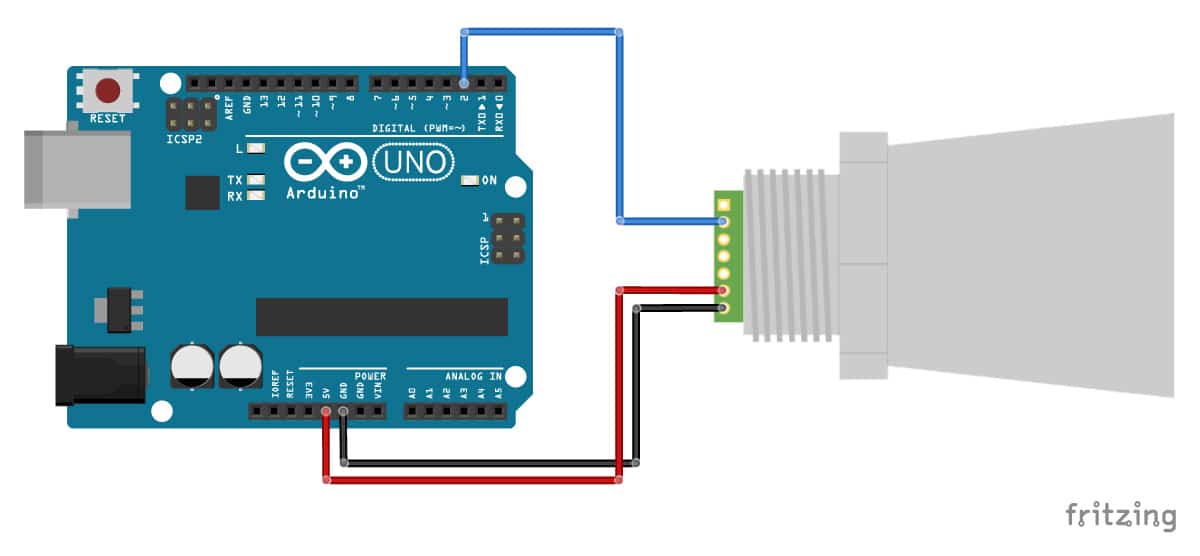
Pin On Arduino

Opto Isolator Driving A Tip120 Npn Darlington Transisotr Teknoloji Arduino Elektronik

In this article i will be providing.
Mb 1000 arduino wiring diagram. Arduino ultrasonic sensor mb1040 lv maxsonar ez4 by maxbotix the maxbotix inc maxsonar ultrasonic sensor line has become a very popular sensor for operation with the arduino micro controller. Maxbotix mb1240 with momentary push button and arduino wiring diagram. As mentioned in the introduction maxbotix sensors can be operated in different modes. If you are trying to get a second usb serial port between the computer and the arduino why are you going through rs232 instead of using a ttl to usb converter between the arduino and the pc.
In this example we will be using a momentary push button to trigger the sensor. With three simple interfaces it is easy to connect a maxsonar to an arduino. Once the example code also shown below is loaded into your ide click on the upload button given on the top bar. 360icon november 10 2016 4 56pm.
You can buy these nice round push buttons on amazon that you can just plug into a breadboard. This is just test. It will work with the arduino based controller as well i have one myself works great i dont have a wiring diagram handy there is a post about it on hear somewhere. Fritzing is an open source hardware initiative that makes electronics accessible as a creative material for anyone.
The cable is called wipe patch cord straight thru cable. The ethernet cable used to wire a rj45 connector of network interface card to a hub switch or network outlet. Pinout of ethernet 10 100 1000 mbit cat 5 cat 5e and cat 6 network cable wiringnowdays ethernet is a most common networking standard for lan local area network communication. We offer a software tool a community website and services in the spirit of processing and arduino fostering a creative ecosystem that allows users to document their prototypes share them with others teach electronics in a classroom and layout and manufacture professional pcbs.
Wiring connecting maxbotix mb7389 to arduino uno. Arduino uno is programmed using arduino programming language based on wiring. I should to connect arduino with some touch panel which have rs232 db9 port. Connect one of the legs to ground and the diagonally opposite leg to arduino pin 4.
The wiring diagrams below show you how you can connect the mb7389 sensor to the arduino for analog voltage or pulse width operation. But the main problem is that to measure the battery voltage i need a voltage divider about 1 2 so that arduino can handle up to 15v. I want from arduino to measure the battery voltage 2p3s li ion battery pack and shows on oled the battery voltage.

Pin Oleh Alex Harijanto Di Mikrokontroler

Pic16f84a Digital Clock Schematic Com Imagens Esquemas Eletronicos Engenharia Eletronica Circuito Eletronico
Arduino Light Sensor Circuit Diagram Using Ldr And Relay With Images Elektronika

Pin On Electronica

17 Clever Tube Wiring Diagram Samples Nixie Tube Electronic Schematics Tube

Arduino High Speed Oscilloscope With Pc Interface Arduino Home Automation High Speed

Sirine 3 Suara Suara

How To Make A Simple Servo Motor Tester Circuit Circuit Tester Circuit Diagram
